Blog

  • Water Level Detector

    Water Level Detector

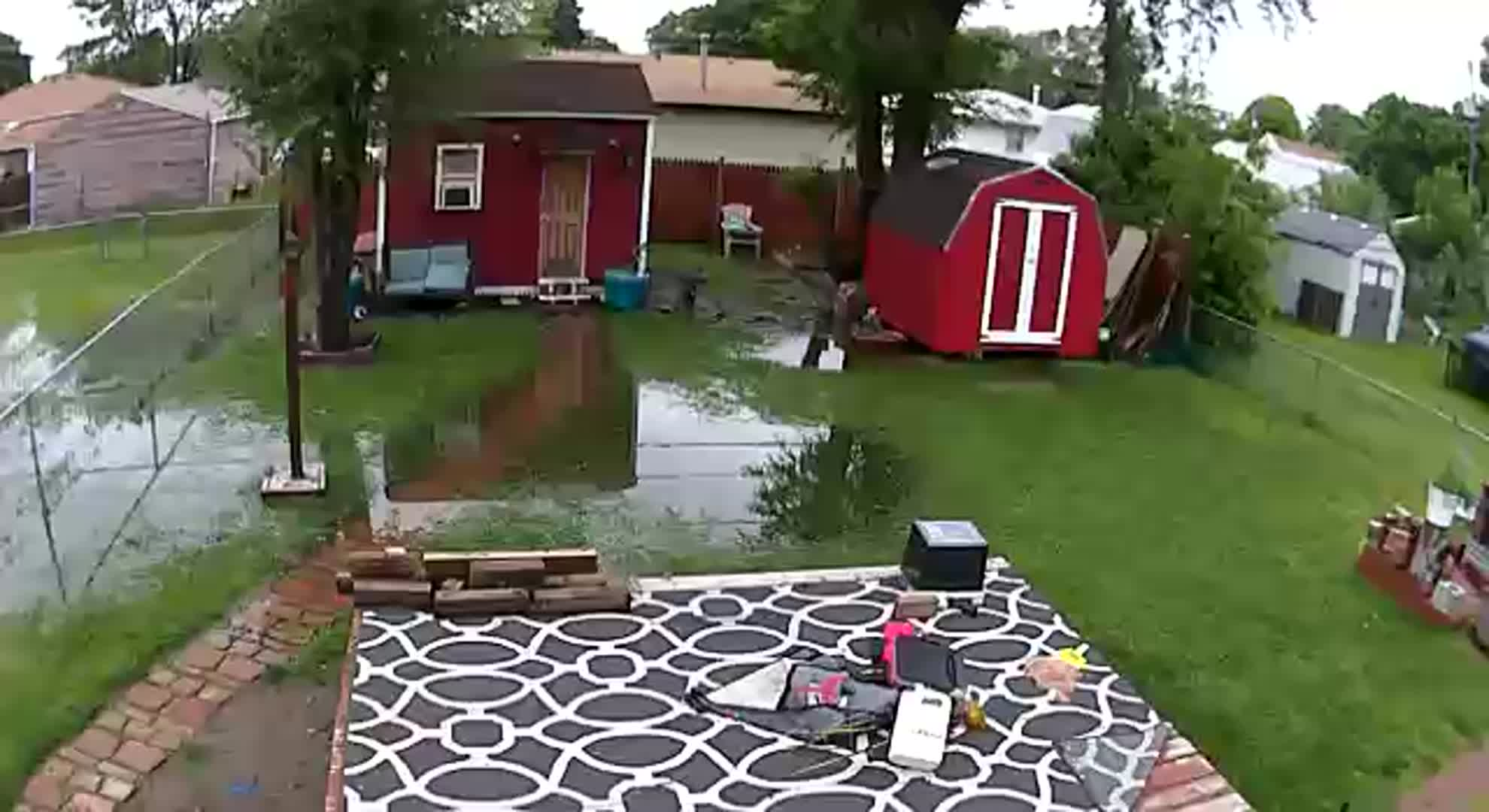
    Lots of rain in Iowa lately. Lots of flooding also. In Council Bluffs, it’s not rare to see people emptying crap out of their basements after a good rain.  Here is a shot from my backyard security camera from just last week.

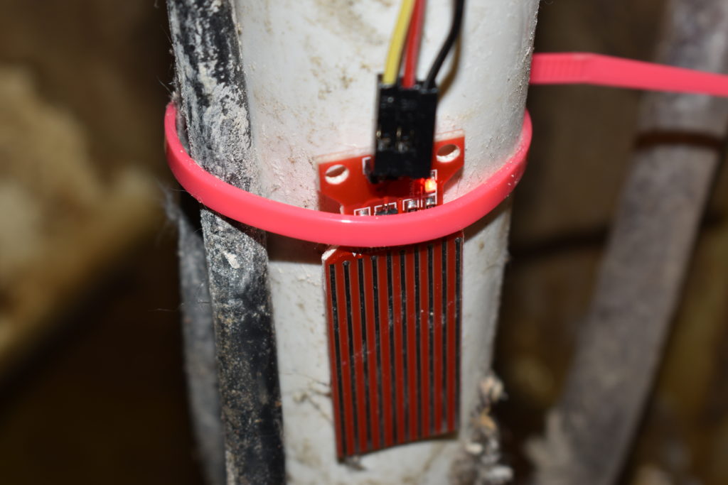
    So while I avoid a flooded basement for the most part, I have leaks of the wazoo. I have had the unfortunate pleasure of having either my sump pump floater getting stuck or simply failing which results in more than a few puddles of water. I am sick of having to worry if something is going to go wrong when I am sleeping or when I forget to check the basement so I built a simple water level detector with a water level sensor.

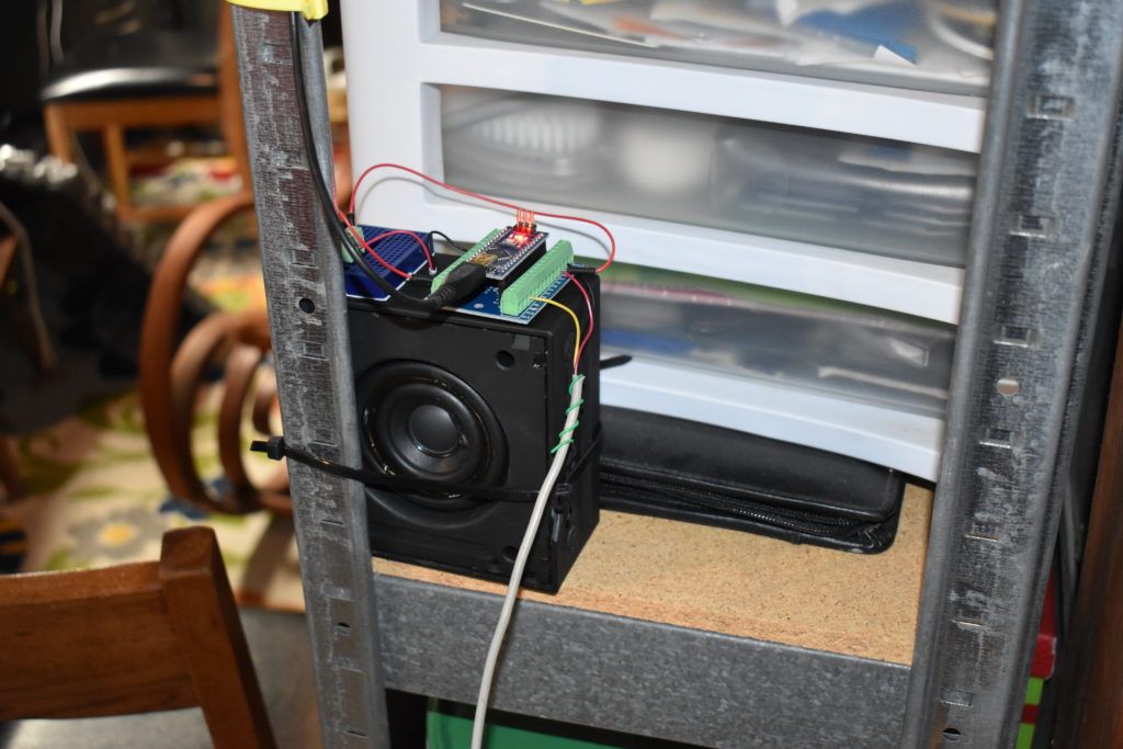
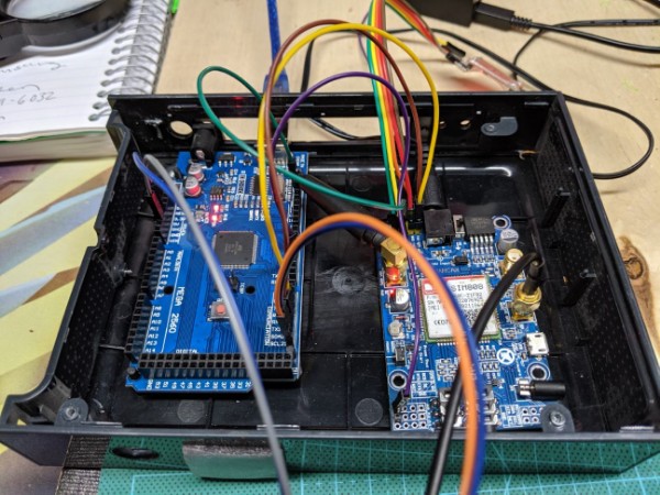
    Using an Arduino Nano microcontroller and some other parts I created something that would set off an alarm if the water got too close to the top of my sump.

    Parts List

    • BC547 Transistor
    • 100 ohm resistor
    • Arduino Nano
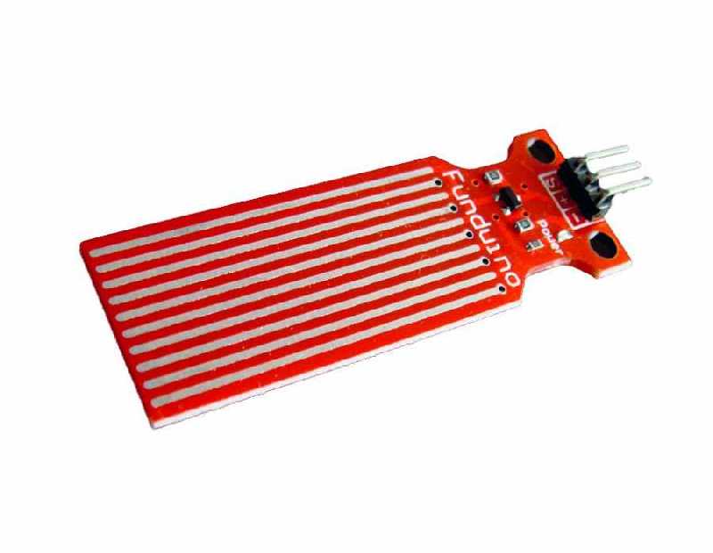
    • Funduino Water Level Sensor
    • Salvaged 3 ohm speaker

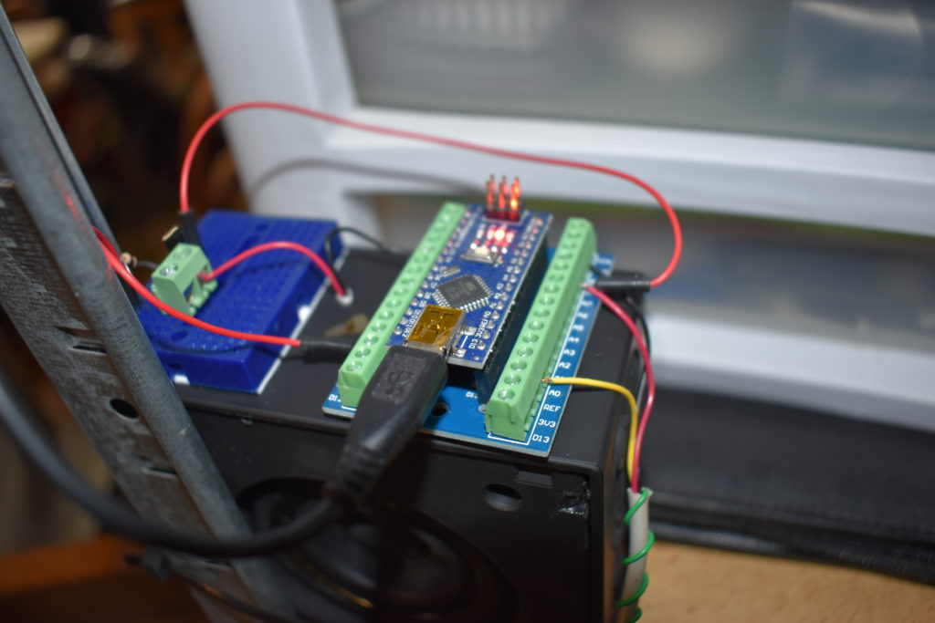
    After wiring up the water sensor and checking on a serial monitor what the analog value would be when water first touches the sensor and what value when water is dripping off of it I programmed the Nano to set off a nice loud alarm.

    Arduino’s only put out 5 v at their output and that results in a ridiculously quiet alarm which is why I put a cheap transistor into the circuit. The result is something I can hear from upstairs and would probably wake me up at night.

  • Stuff Happens

    Stuff Happens

    A nice gentleman brought in a Samsung Galaxy Tab S TM-807V with a severly cracked screen. It was also very attached to the 3rd party plastic case/cover it was in. It was clear the Tab had not been removed from its case in a very long time.

    The first warning signs should have been how deep the damage went. If you click the images you will see red circles highlighting the damage. The screen wasn’t just cracked, it was degraded. In the upper lefthand corner the screen was missing and you could see the underlying component. Tabs, and tablets in general, have an adhesive that runs all around the outside to keep the digitizer (the part that translates your touch into data) in place.

    This usually isn’t a problem until you find out that the screen isn’t actually sitting on top of the actual display and that it is glued to it. Replacing a screen is actually pretty easily and done fairly cheaply I might add. If you didn’t know how to do it you could find many YouTube videos showing you how.

    In short, you take a heat gun around the outside perimeter of the device to soften the adhesive. Then you use a small plastic prying tool to gently lift it up. The idea is to remove the screen in one piece despite the broken glass. Generally you can put tape on the screen to help keep the glass in place if you feel that will be an issue.

    But this device had shattered to the substrate of the display and exposed the adhesive beneath it. So when I went to lift the screen off I also actually lifted this glass shell off the OLED.

    When the screen is so severly damaged with thousands of glass shards AND it is adhered to the screen, it makes the replacement difficult and prone to failure. While a repair of this magnitude is feasible, it would have just meant the replacement of the entire display unit and not the digitizer atop it. 

  • Analog Meter Battery Cover

    Analog Meter Battery Cover

    So I bought this analog multimeter at a pawn shop for $5 and it was missing the battery cover. It seemed like a perfect opportunity to 3D print something practical instead of Star Trek ships.

    I took CAD in college and I was pretty good at it. So I fired up  AutoCAD 2019 and started messing around with it. Admittedly, it was much different than what I was use to but I have always been a quick study.

    After taking some careful measurements with my micrometer and ruler and scribbling down the notes of how I intended on tackling this I dug my heels in. It took me a few days just because AutoCAD 2019 is so much different than the CAD programs I have used. They say ‘measure twice, cut once’ and that adage couldn’t be closer to the truth when it comes to designing something and then waiting a couple hours for it to print. While you can adjust minuscule miscalculations with a file and some sandpaper — a major one means you will have to alter the design and print again.

    My 3D printer is a Creality Ender 3 with a BLTouch automatic leveling sensor. After 30 minutes of tenuous worrying that I had gotten it all wrong I had a battery cover

  • GPS Tracker

    GPS Tracker

    [et_pb_section fb_built=”1″ _builder_version=”3.21.4″][et_pb_row _builder_version=”3.21.4″][et_pb_column type=”4_4″ _builder_version=”3.21.4″][et_pb_text _builder_version=”3.21.4″ text_font=”||||||||”]

    I am developing this GPS Tracker using an Arduino Mega 2560 and SIM808 GSM/GPRS/GPS Cellular Module. The SIM808 is basically the same sort of board you might find in a cellphone. The price varies depending on the version of the board you get. This one is a development board and can run you anywhere from $30-$40 bucks depending on who is trying to rip you off. The Arduino Mega is a microcontroller board based on Atmega 2560 microcontroller.

    I use a variety of different microcontroller boards and I am always giddy to try out something new. In general, these things are used to integrate with other devices.

    The operation of this system is pretty simple and can be configured in a myriad of ways. The board wakes up every 30 minutes and looks for satellites. When it has a 3D fix it sends the data to one of my servers where it is stored and shown on a map then it goes back to sleep.

    I am using a 11v LiPo battery to power the arduino and a 3.7V LiIon battery to power the GPS. The LCD display is just for debugging purposes. The data is sent using a Google Fi data-only SIM card.

    Communication between the arduino and GPS is facilitated by sending AT commands to the sim808 board which pretty much controls every aspect of the process from communicating the the cell network, http protocol for sending data, and the interfacing with the GPS satellites.

    While the project was a success there are many considerations that makes this specific GPS board unsuitable for long-term application — mainly its size. I might as well glue a normal cell phone to the car.

    Alas, the project gave me some practical experience and code for future possible projects. One such project is making a remotely controlled clone of a Mars rover.

    [/et_pb_text][/et_pb_column][/et_pb_row][/et_pb_section][et_pb_section fb_built=”1″ _builder_version=”3.21.4″][et_pb_row _builder_version=”3.21.4″][et_pb_column type=”4_4″ _builder_version=”3.21.4″][et_pb_gallery gallery_ids=”265,269,267,305″ _builder_version=”3.21.4″ title_font=”||||||||” box_shadow_style_image=”preset4″ box_shadow_horizontal_image=”4px” box_shadow_vertical_image=”4px” box_shadow_blur_image=”7px” box_shadow_color_image=”rgba(25,25,25,0.63)”][/et_pb_gallery][/et_pb_column][/et_pb_row][/et_pb_section]